Acura RSX DIY: Knock Sensor (& Starter) Replacement - Base Model
* Starter and knock sensor are right next to each other, so the work to get to them is the same.
My check engine light had come on in my '02 Base auto, so I went straight to AutoZone for a free code scan...
P0325
Definition: Knock sensor (KS) circuit malfunction
Probable cause: a. Open or short circuit condition b. Poor electrical connection c. Faulty knock sensor
My car otherwise ran perfectly. A bad knock sensor is supposed to throw you into a limp mode where you run really rich (noticeable drop in fuel economy) and horsepower is cut. I experienced none of that. However, when I replaced my starter a few months back, I got brand new OEM battery harnesses at the same time, since my car is from the east coast and is pretty rusty under the hood. The knock sensor connector is part of that, so I was pretty sure I had a good connection. I assumed the sensor must be on its way out.
AutoZone wanted $55 for a new sensor, while Delray asked about $60 shipped after the CRSX discount. May as well go OEM. If I had known these tend to fail about the same time as the starter, I'd have ordered this cheap thing at the same time. Thanks to a friend working at AutoZone, I was able to get a reman starter for $100; would've been about $120 otherwise.
After following the factory service manual and taking apart much of the front end of the car to get at the starter, I found ways to save time this go-round. Took me two hours including stopping to take photos and write down quick notes for this DIY.
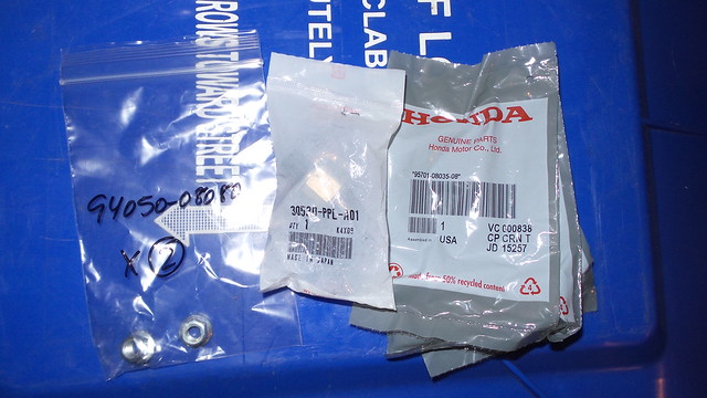
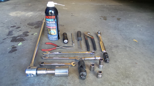
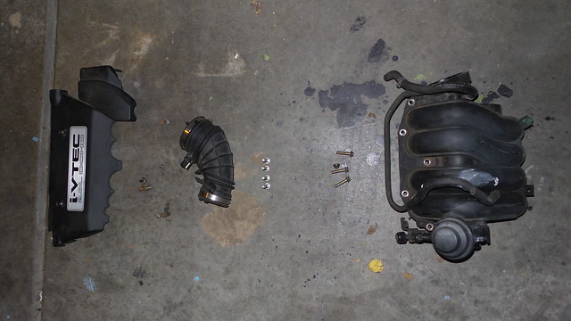
Tools & Parts Needed: - Knock sensor (part no. 30530-PPL-A01 for Base model only) - 10 mm socket & combination wrench - 12 mm socket & combo wrench - 17 mm socket (for starter only) - 27 mm socket (for knock sensor only) - Ratchet - Short extension - Wobble bit - Phillips screw driver - Needle-nose and standard pliers - Magnet...on-a-steek (optional) - Flash light (optional) - Loctite Freeze & Release (if your shit's rusty, 'cos WD-40 and PB Blaster suck)
(sensor in the middle, plus replacements for my corroded manifold bolts/nuts)
TIP: Organization is always a helpful tool when working on a car. As I removed things, I set them on the ground in that order, in an out of the way area, to help with reassembly.
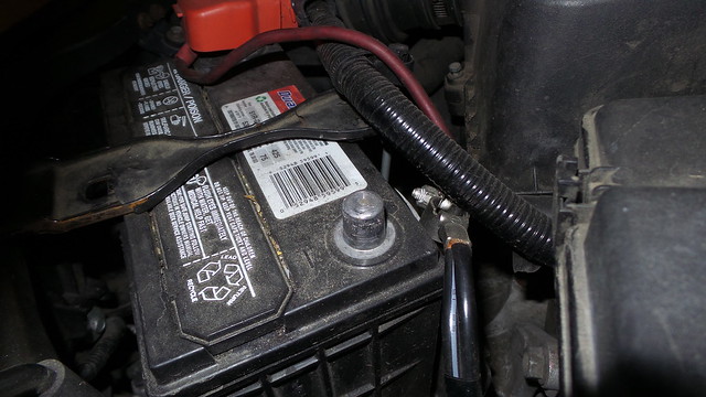
Step 1: Disconnect the Negative Battery Terminal
You always want to disconnect the battery when working with electronics to keep voltage spikes from possibly damaging equipment. In this case, you're probably changing the sensor because your CEL is on, and it takes 20 minutes of battery disconnection to clear soft codes anyway. It's a 10 mm nut.
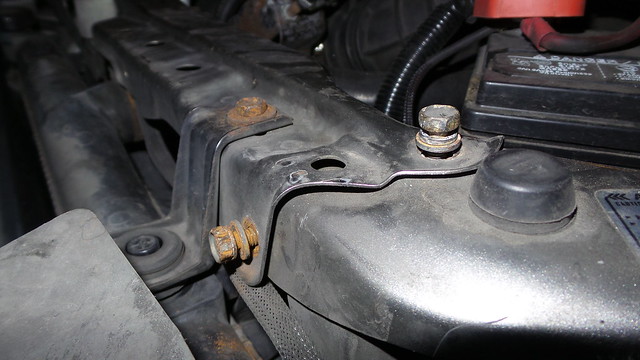
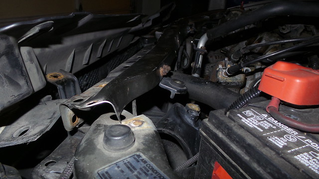
Step 2: Move Radiator Support for Clearance
The factory service manual would have you remove the front bumper and all this other tedious crap, and the extra work is just not necessary. All you have to do is move the center radiator/core support brace forward a bit so the intake manifold has room to exit the bay.
First, there are three 10 mm bolts at either end, holding the brace to the chassis, and the radiator to the brace.
Then you've got two more 10s, securing both the intake ducting and the A/C line to the brace. It's a tight pull, but you can now move the brace up and over the chassis for the couple inches of needed room later.
7.29.2019 Edit: When I did mine, I didn't need to completely remove the upper radiator support brace to have enough room to work with. However, EJP914 let me know that that might not be the case for everyone, and adds this:
There is one more 10mm bolt that has to be removed before you can lift up the radiator top brace and pull the whole thing forward. That bolt is at the very bottom of a vertical brace that is attached to the middle of the top one. I removed it from under the car. You have to remove the splash shield to get to it. You might get it from the top but its a tight squeeze.
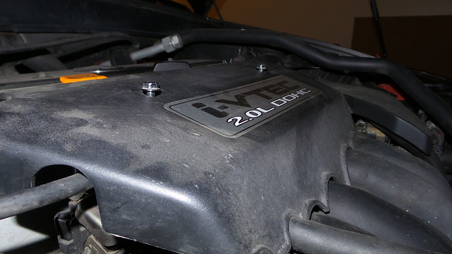
Step 3: Remove the Intake Manifold Cover
Simple. There are two shiny 10 mm bolts holding on the decorative "I-VTEC" piece.
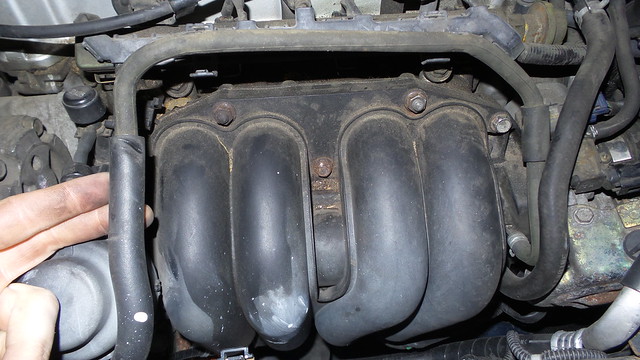
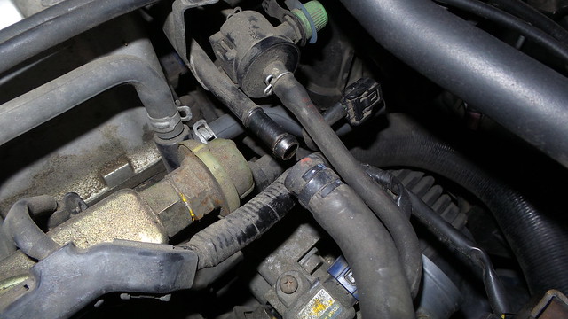
Step 4: Remove the Manifold Vacuum Hose
There is a vacuum hose circling around the top of the manifold. Pick an end, either end, and use your pliers to disconnect that one end from the car. I went with the left side so it comes out with the manifold.
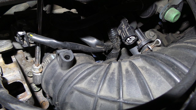
Step 5: Remove the Intake Elbow
Loosen the hose clamps/jubilee clips at both ends of the elbow with the screw driver. Disconnect the Intake Air Temperature sensor on the inside of the bend, as well as the vacuum hose immediately below that. Now you can prize the elbow from the car.
Step 6: Disconnect the Coolant Hose
Use your pliers to free the coolant hose located by the end of the fuel rail and above the throttle body. You only need this one end disconnected... I didn't have anything leak out of mine :ugh:
Step 7: Unbolt the Throttle Body
The throttle is held on by four 12 mm bolts. The stick magnet will help keep you from dropping them into that black hole that is the engine bay. Once the bolts are out, separate the throttle from the manifold and just let it hang there. No need to deal with the sensor connectors or coolant lines.
(no pic, sorry)
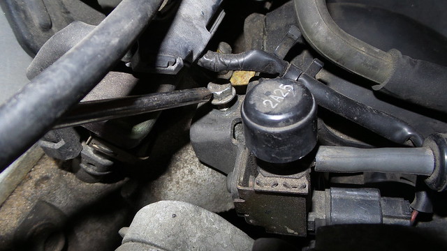
Step 8: Isolate "the Diaphragm"
There's this plastic diaphragm thingy on the passenger side of the manifold... I don't know what it is (I'd guess either cruise control or the motor for the butterfly valves in the manifold), but it's got associated parts that are tying the manifold down. First, remove this 10 mm bolt, move the bracket out of the way, then put the bolt back in its hole for now so you don't lose it.
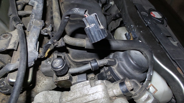
With the bracket loose, you can free the related connector and its wire from the manifold... use the needle-nose to get that harness clip off properly:
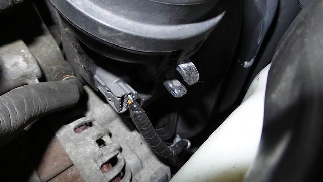
Lastly, disconnect the plug under the large diaphragm:
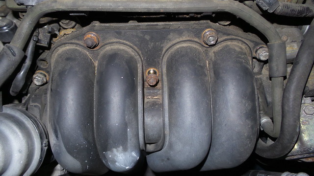
Step 9: Remove the Plastic Half of the Manifold
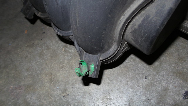
Remove the five 12 mm bolts and nuts holding it on and it should be free to pull from the car. Watch out underneath the manifold for a green harness tie; cut it or properly remove the clip from behind with your needle-nose.
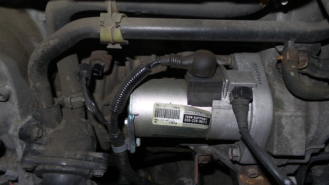
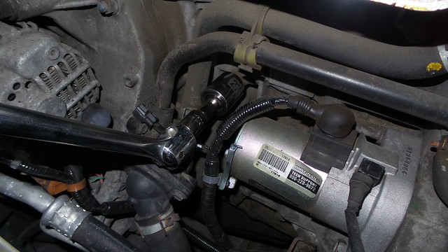
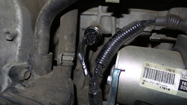
Step 10: Change the Knock Sensor / Starter
In the photo below, you'll see the disconnected knock sensor on the left. Use your 27 mm socket to remove the old sensor and secure the new one.
For the starter, you're looking at two charge harness connectors, two long 17 mm bolts securing it to the block, and an 8 mm bolt holding the little harness bracket on.
Step 11: Reassembly
Parts go back on in reverse order. Once Humpty Dumpty is back together again and the battery is finally reconnected, let it idle for a bit or go for a test drive to confirm the CEL doesn't come back on.